Friday, 7 August 2009
Receiver update
Next week we will be begin working on the transmitter, which won't be on stripboard like our receiver, but will be a proper PCB. There are a quite a few reasons for this, but weight and size are a major factor. We will also be taking our first look at the Canon A560 camera and seeing what its capable of.
Thursday, 6 August 2009
New board and an update on software
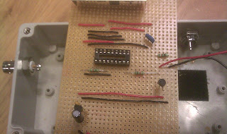
As I suspected, the stripboard could not take the pain of further re-soldering, so a new board had to be acquired. This time the whole board is being laid out first, (as you can see from the photo), and will be soldered in one go. I’m fairly confident that the major components (the IC’s) will have survived – but we won’t know for sure until tomorrow. Lets hope Friday is third time lucky.
Andy has been putting in the hours on the tracking software and the latest news is that it can now error check the data that is received from Zephyrus 1. During the flight it’s likely that the radio range will be close to its limit and, as a result, some information may be corrupted. In that instance, we don’t want to be chasing shadows – we want to know for sure that the data we get back is good. Thanks to Andy’s software, any points plotted on Google Maps will be pre-checked giving us full confidence in where our payload is.
Wednesday, 5 August 2009
The joys of resoldering...
Meanwhile, Phil has been investigating parachutes and Andy is developing tracking software that will, among many other benefits, allow multiple recovery teams access to live location information.
Receiver complete
In other news from today, Windows Mobile continues to impress. One of our major concerns is that GPS equipment will fail due to ITAR/COCOM restrictions. Thankfully a free (and powerful) scripting utility for WinMo allows us to restart the GPS whenever we like. I'll cover what we are using, and how we are using it, in a future post. No matter how good the radios are, Windows Mobile is booked on the flight.
Monday, 3 August 2009
Status update
Balloon - FLIGHT READY
Capsule - DESIGN PHASE
Parachute - OUTSTANDING
Phone - FLIGHT READY
Camera - PURCHASED; AWAITING DELIVERY; FIRMWARE TO BE LOADED & TESTED
Transmitter - PROTOTYPE PHASE; FIRST TEST COMPLETE
Receiver - PROTOTYPE TESTED OK; BUILDING PRODUCTION VERSION
Rx Antenna - COMPLETED BUT NOT FULLY TESTED
Tx Antenna - OUTSTANDING
Sunday, 2 August 2009
Voltage regulator
Saturday, 1 August 2009
A better receiver
The prototypes work, but are fragile and cumbersome. Having the receiver in a single, easy to transport and handle unit with sockets for antenna (BNC) and serial (DB9) will make subsequent test runs much smoother. As you can see here, the work on such a unit is just beginning.


